
Problem Detail: I’m going through Dr Joost-Pieter Katoen’s slides and stumbled upon this: 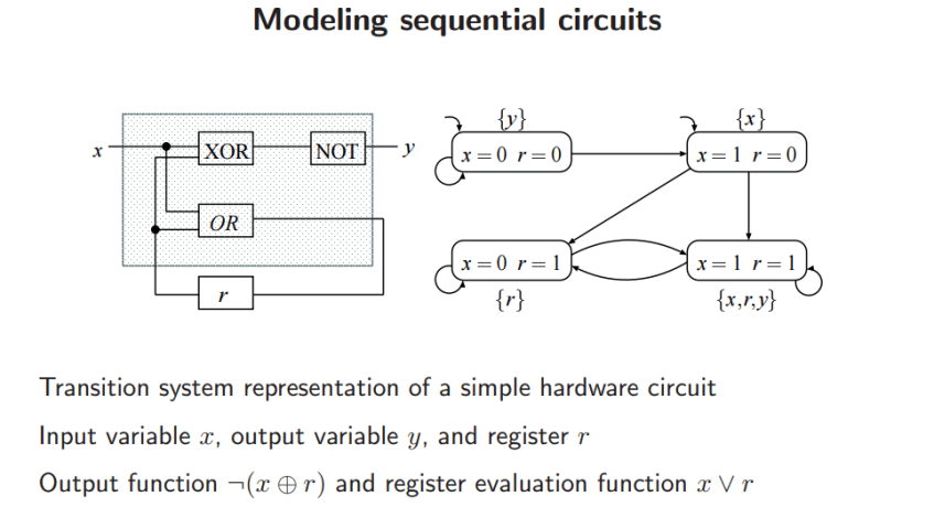 For some reason I can’t quite make out how the transition system relates to the sequential circuit. If I had a question for instance that asked me to convert the circuit into a TS, what steps should I take to approach it (using this one as an example). Grateful for any help.
For some reason I can’t quite make out how the transition system relates to the sequential circuit. If I had a question for instance that asked me to convert the circuit into a TS, what steps should I take to approach it (using this one as an example). Grateful for any help.
Asked By : eyes enberg
Answered By : hengxin
How does the transition system (denoted by $texttt{TS}$) relate to the sequential circuit (denoted by $texttt{SC}$)?
- The states of $texttt{TS}$ are all possible combinations of values of variable $x$ and register $r$ (no output variable $y$) in $texttt{SC}$.
- The label of each state in $texttt{TS}$ consists of all the variables (including the register) which are evaluated true given the valuations in $texttt{SC}$.
For example, ${x, r, y }$ for state $(x = 1, r = 1)$ means that all variables are true according to $lambda_y = lnot (x oplus r)$ and $delta_r = x lor r$ given $x = 1, r = 1$. - The transitions (arcs with arrow) between states in $texttt{TS}$ result from the functions $lambda_y$ and $delta_r$.
For example, $(x = 0,r = 1) to (x = 0,r = 1)$ if the next input bit equals 0.
For more details and a general recipe for modeling sequential hardware circuits as transition systems, please refer to the book “Principles of Model Checking” (Section 2.1.2) by Christel Baier and Joost-Pieter Katoen. The MIT Press.
Best Answer from StackOverflow
Question Source : http://cs.stackexchange.com/questions/41022 Ask a Question Download Related Notes/Documents
